This reminds me to use top gear on the highway and helps me when down shifting to a slow corner or stop.
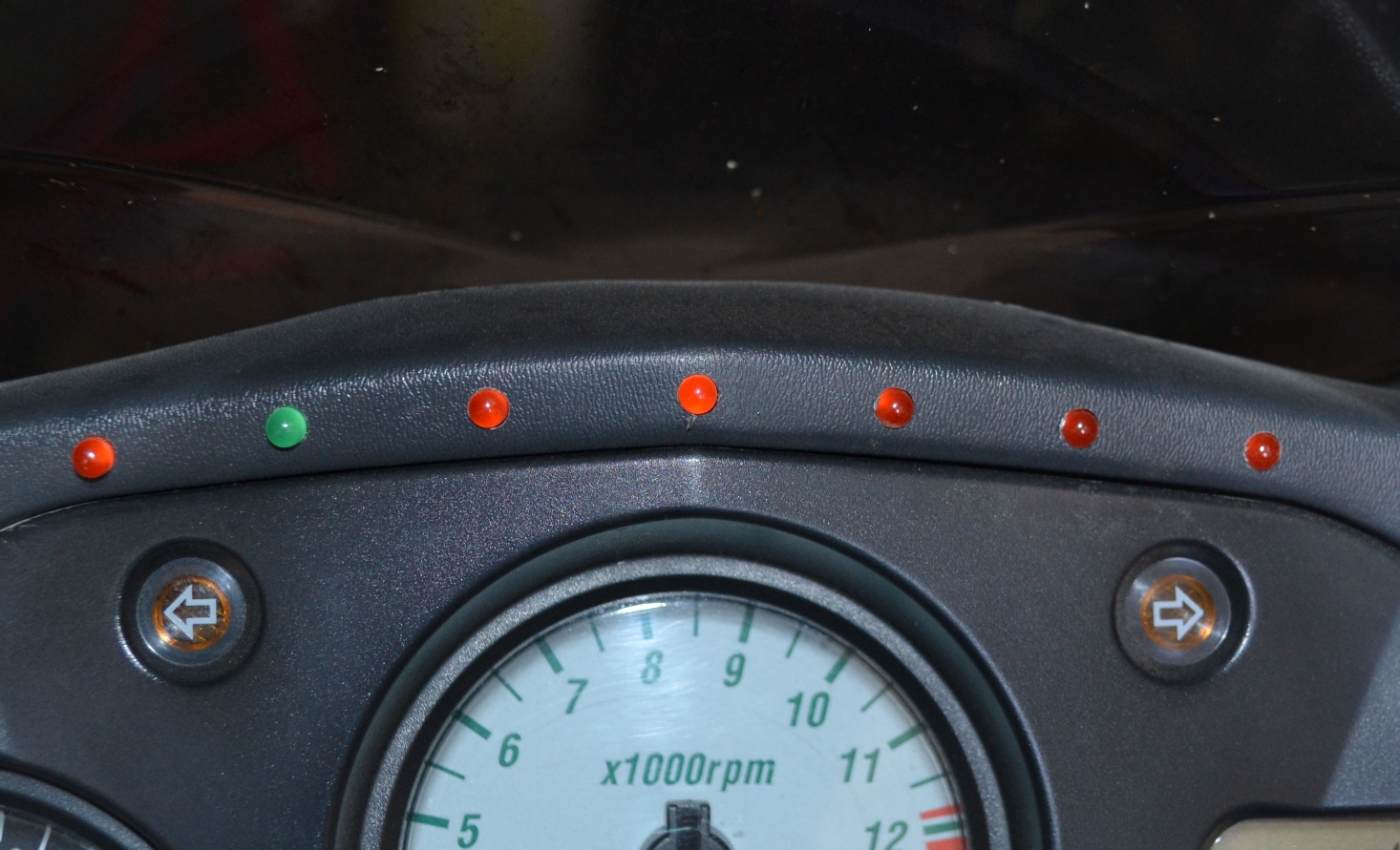
A bead of silicone retains the LEDs and seals the electrical connections.

I had ordered a 5 Volt unit, but a 3.3 Volt unit was shipped. I was planning to used the VCC out from the Arduino to power the Hall Effect sensors, but 3.3 Volts is too low. This necessitated the LM317 Voltage Regulator and associated circuitry.
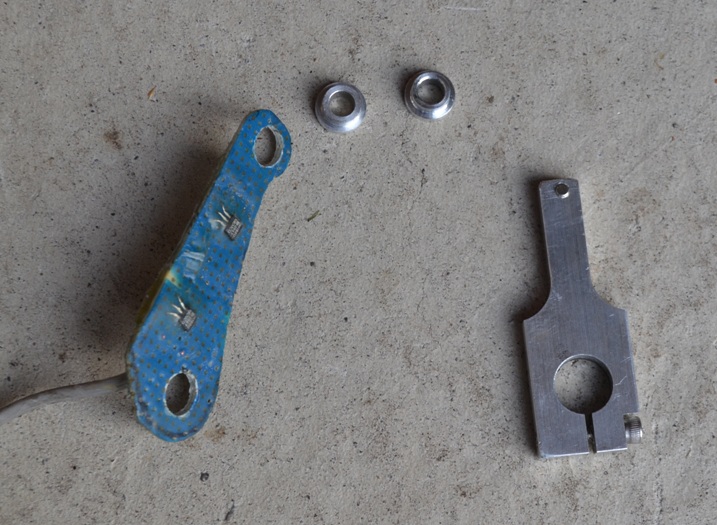
The magnet arm mounts to the shifter shaft inside the shifter.
Since this picture was taken, the 1/8" magnet was replaced with a 1/4" diameter magnet and a steel cover plate with holes (or "windows") was placed over the Hall sensors to improve performance and allow some distance between the magnet arm and the sensor plate.
